Loading...
SPECTER 700 V2 Gasser Build Tips.
Hello Gasser Lovers,
I managed to find some time to shot some photos in order to help all SPECTER 700 V2 Gasser Conversion owners to built this amazing frame with less hassle..
So..
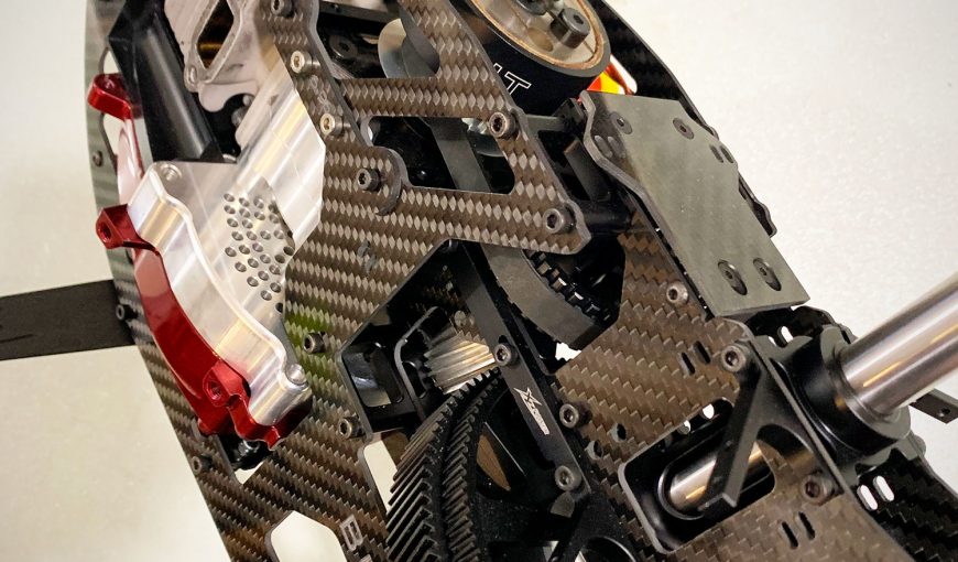
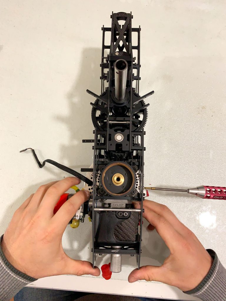
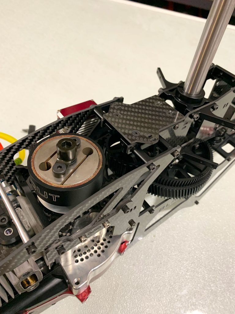
- 1st of all Build the Upper frame like normal and use the new Main Gear included in the kit..
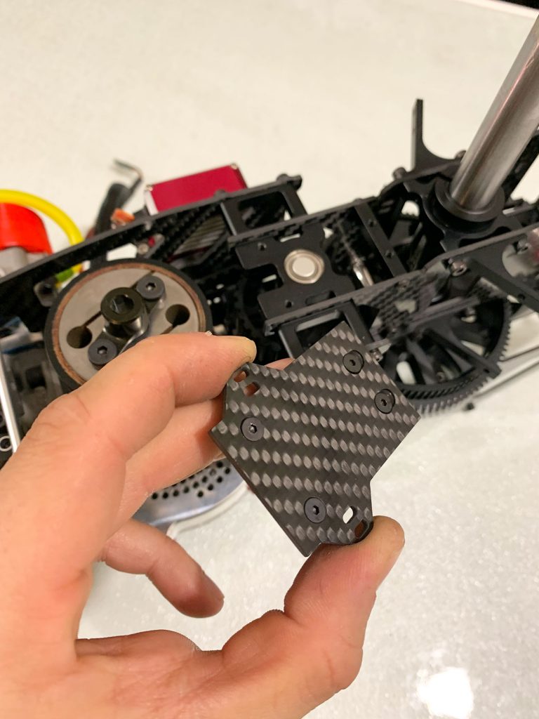
- You will need to trim the original middle carbon plate to size.
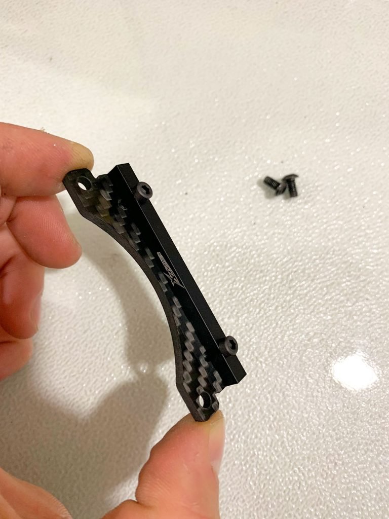
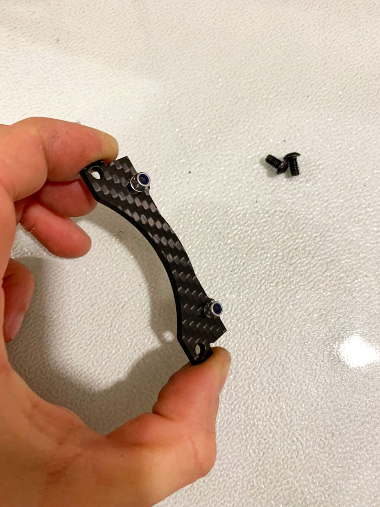
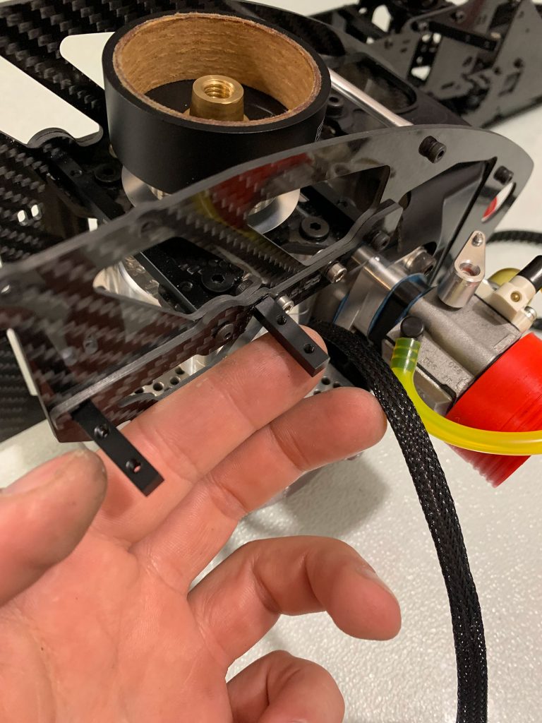
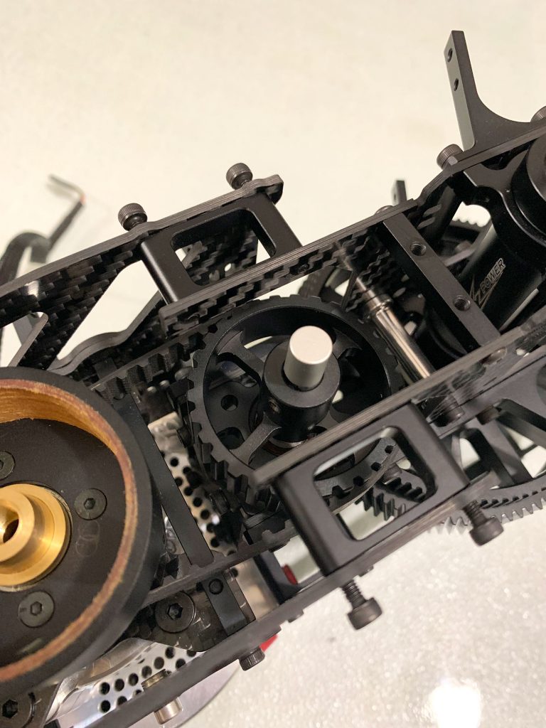
- Use the included pair of black metal braces that secure the upper frame with the lower frame under the main shaft..
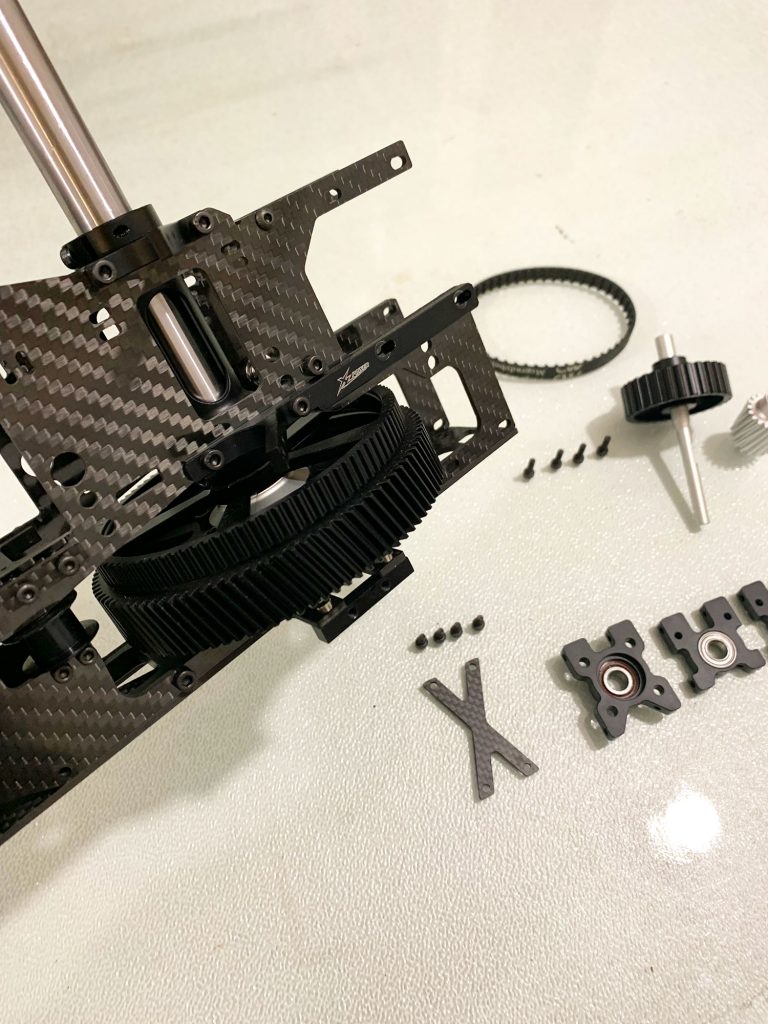
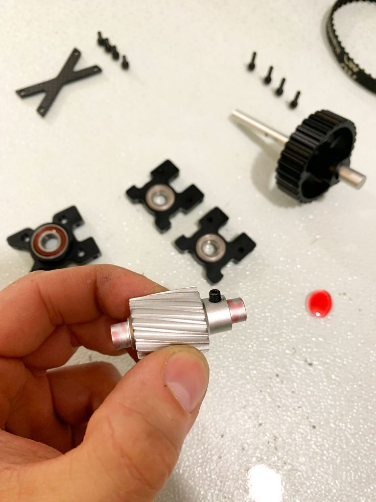
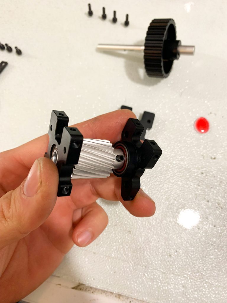
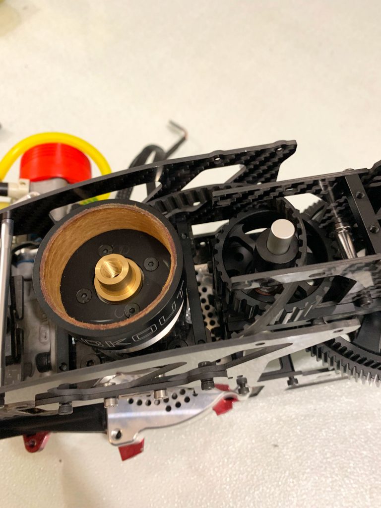
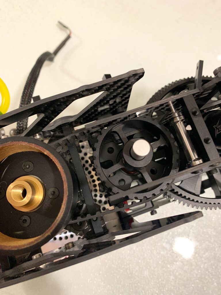
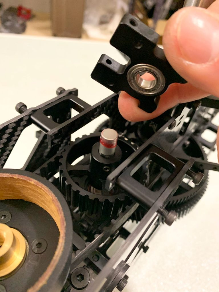
- Prepare the 2nd Stage drive train using the Included Shaft, Pinion Gear and Pulley Gear.. Use lock tite to secure the pinion to the inner bearing races to make sure that the pinion will not spin inside the bearings..
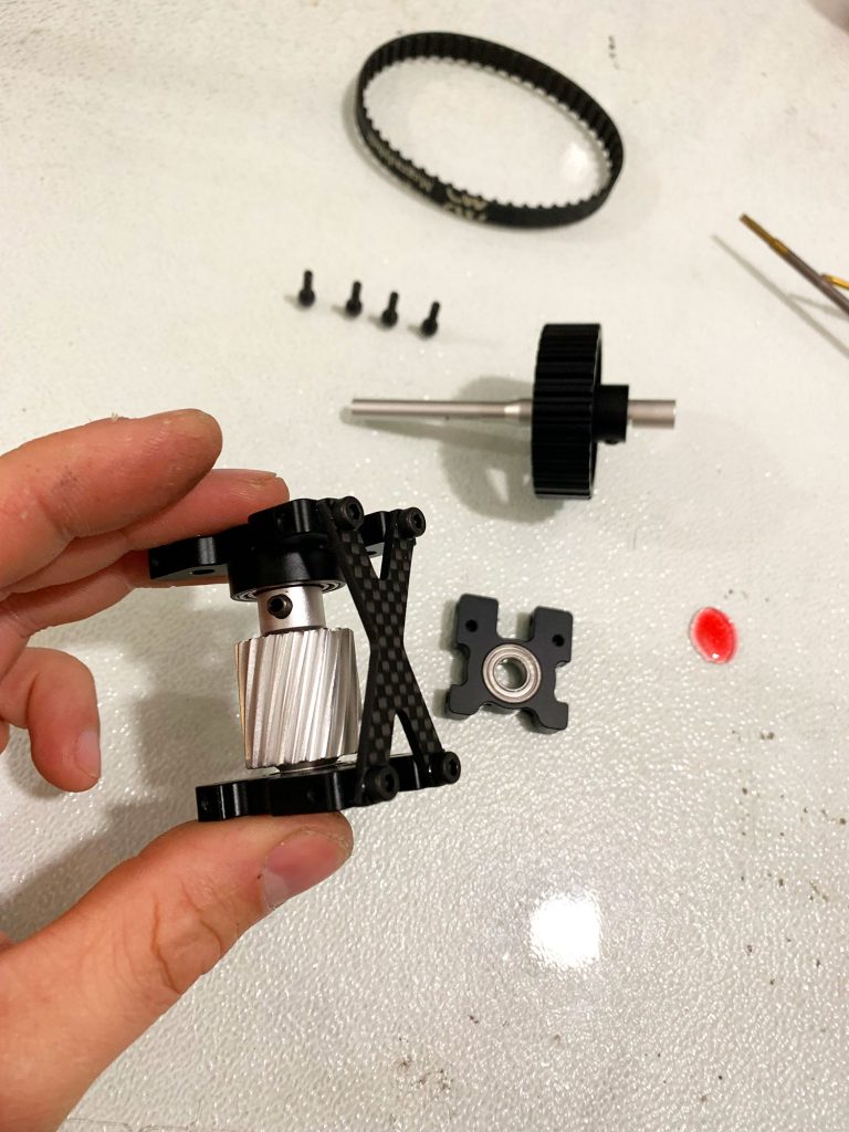
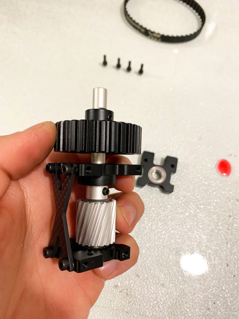
- Mount the Assy on the Upper Frame and use lock tite only at middle bearing block Bolts.
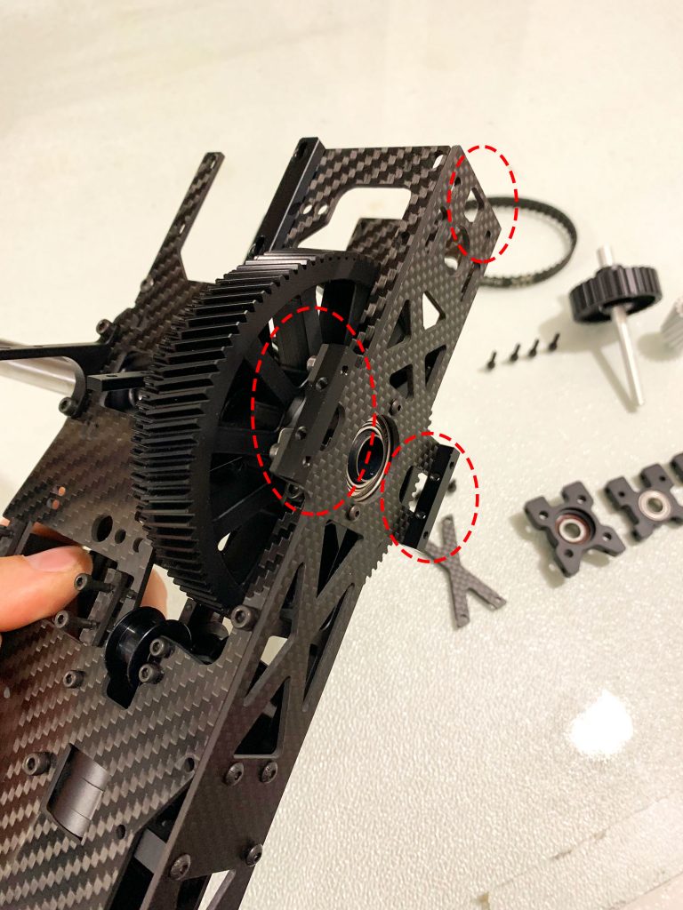
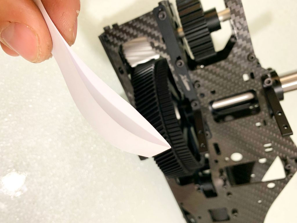
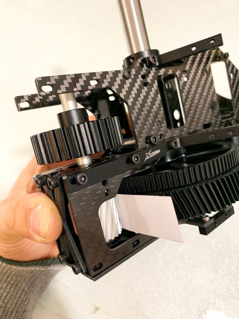
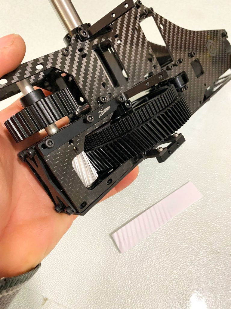
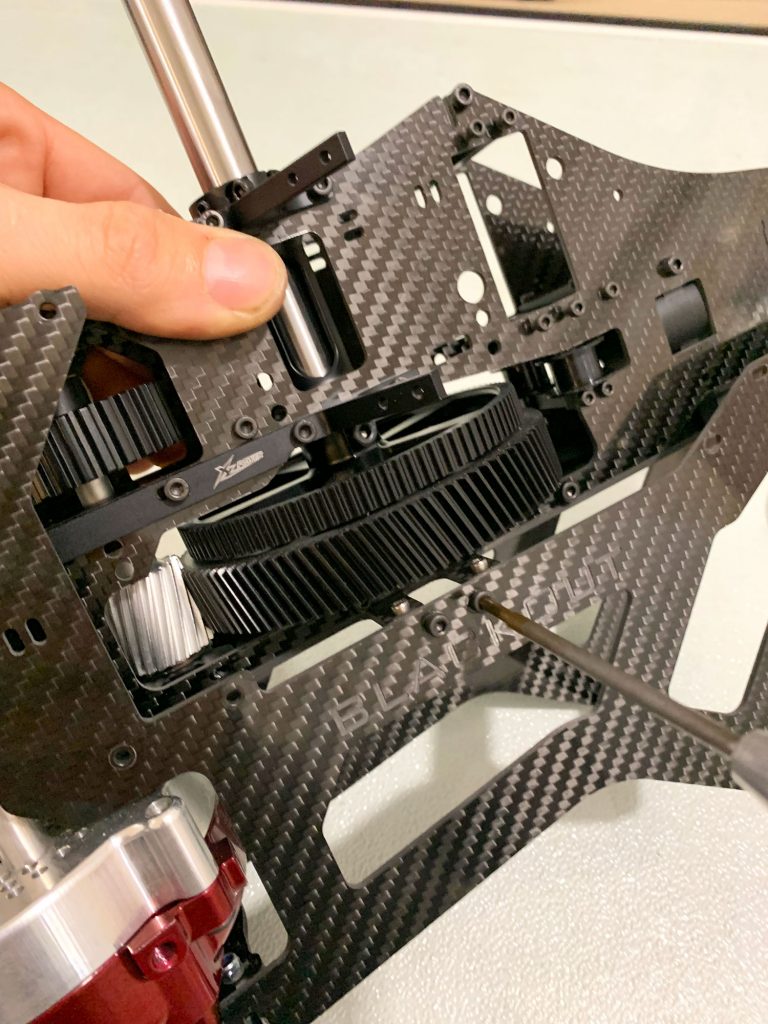
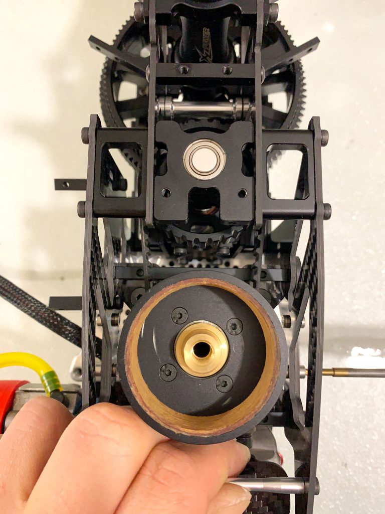
By folding a regular A4 Print Paper sheet you can have the perfect Gear mesh.
Press with your hand the Shaft with the pulley and the pinion gear against the main gear and full tight the 4 bolts with the lock tite. These Bolts are not accessible after the mariage of the upper and the Lower Frames, so you have to do it corect.
Then rotate the gears to remove the paper and you have perfect gear mesh for the 2nd Stage of the drive train ( Gears ).
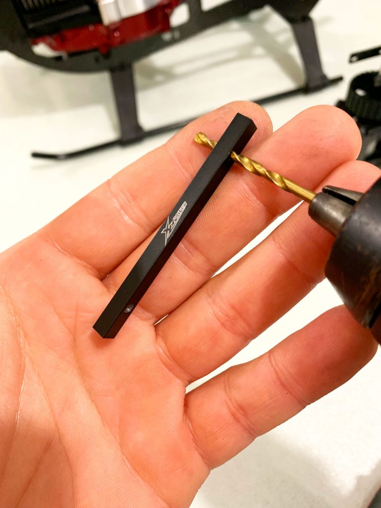
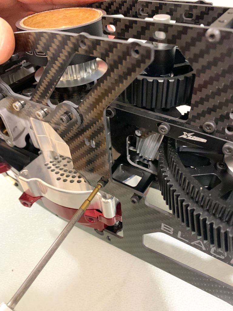
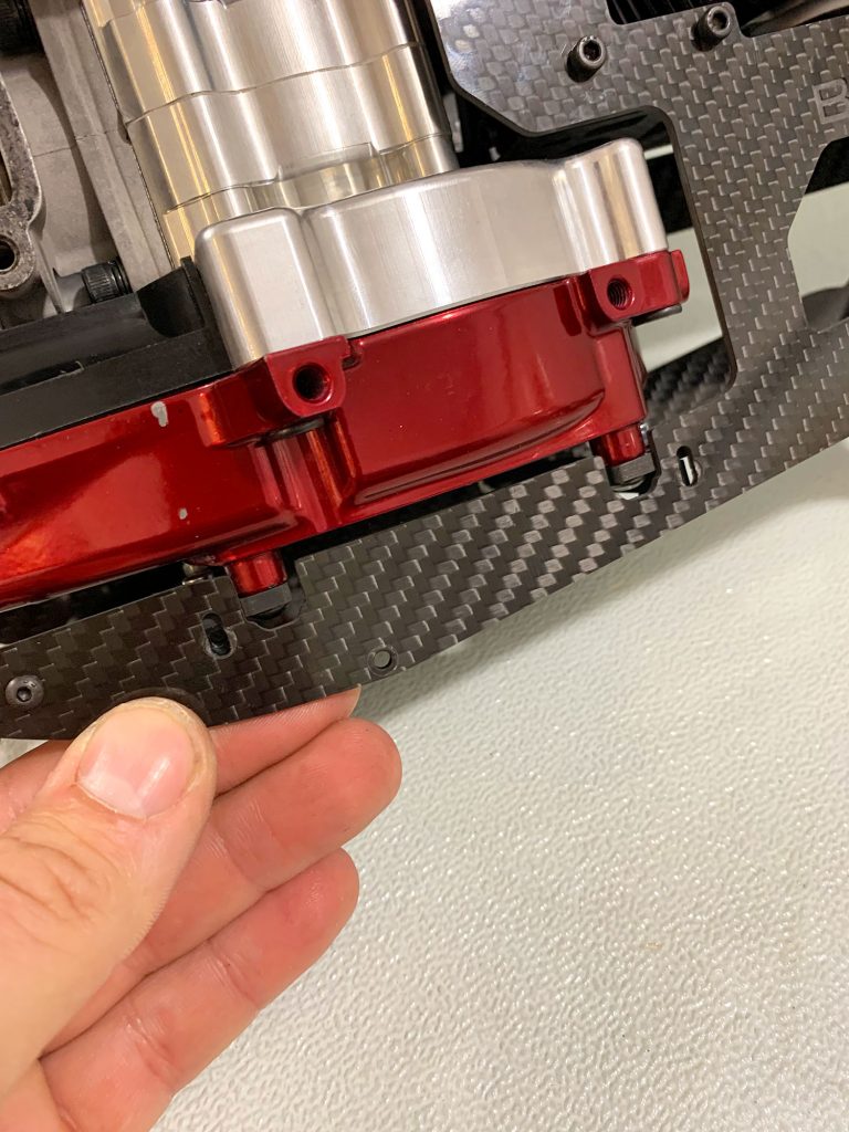
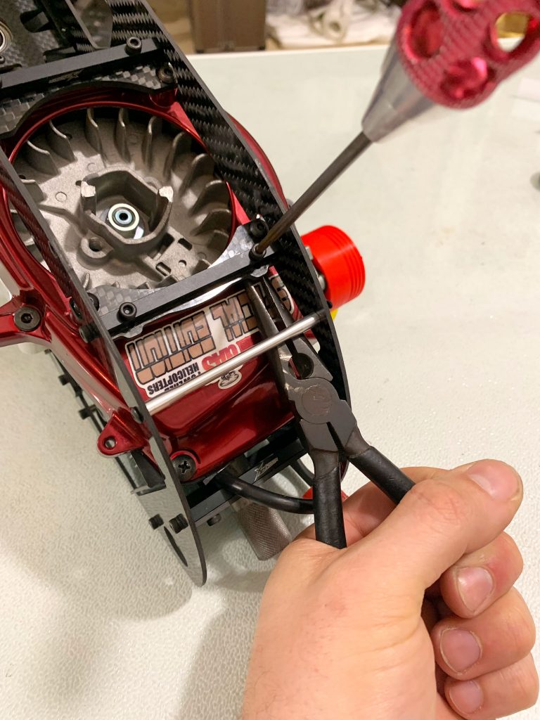
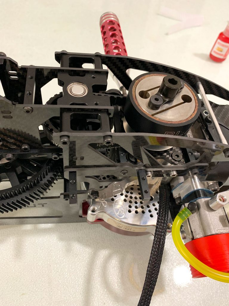
- For the Bottom Engine Mount system you can use the original metal mounts without modding but will be a bit of hassle to align the engine later that you will need to adjust the Belt tension of the 1st stage of the drive train, so i strongly recoment to do this mod as follows..
With a 3MM drill, open the threaded holes and use 4 X M3 12MM long bolts and M3 Nuts as you can see on these pics..
Use Lock tite for the M4 Mounting bolts to secure the carbon fiber parts but keep the M3 bolts with the nuts loose in order to be able to move…
You will full tight them later..

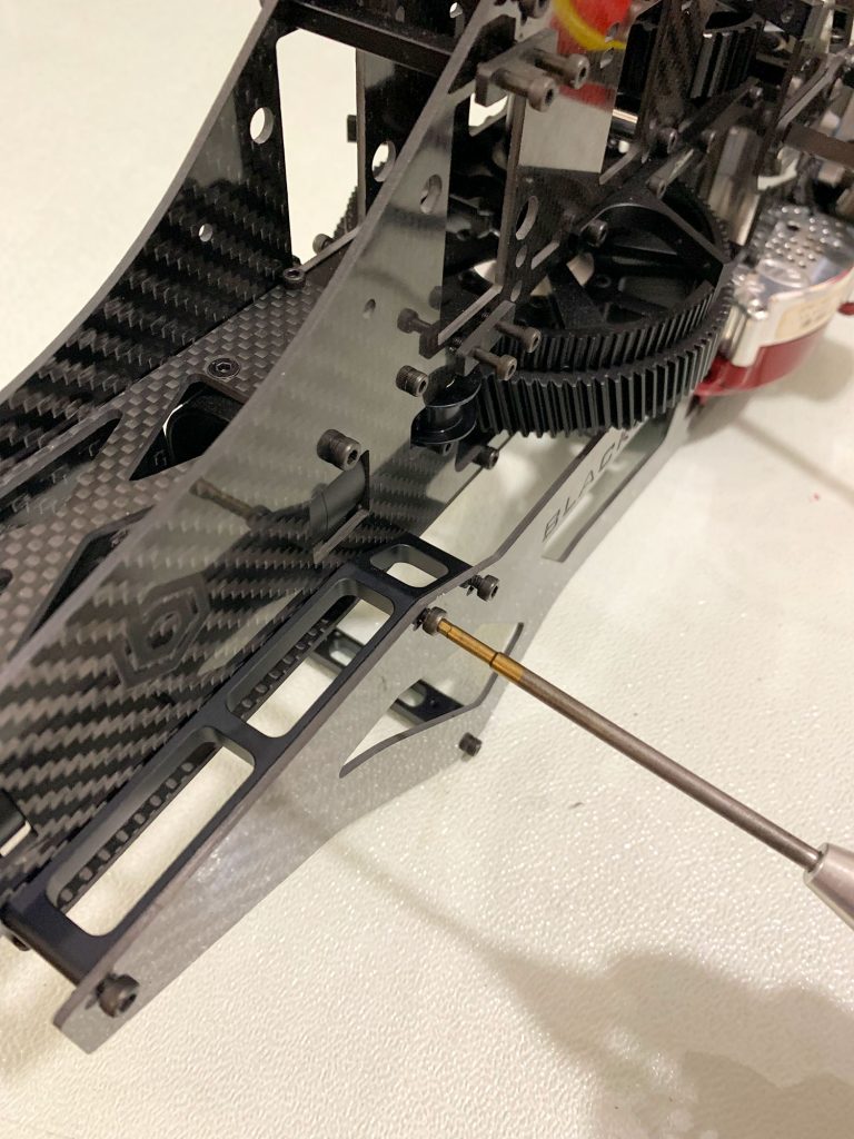
- At the left side of the Lower frame you must mount the Throttle Servo Mounts.
Keep these mounts loose for now.
Next Merge the Upper with the lower Frames together by using the propper M3 Bolts and metal spacers but keep them all loose..
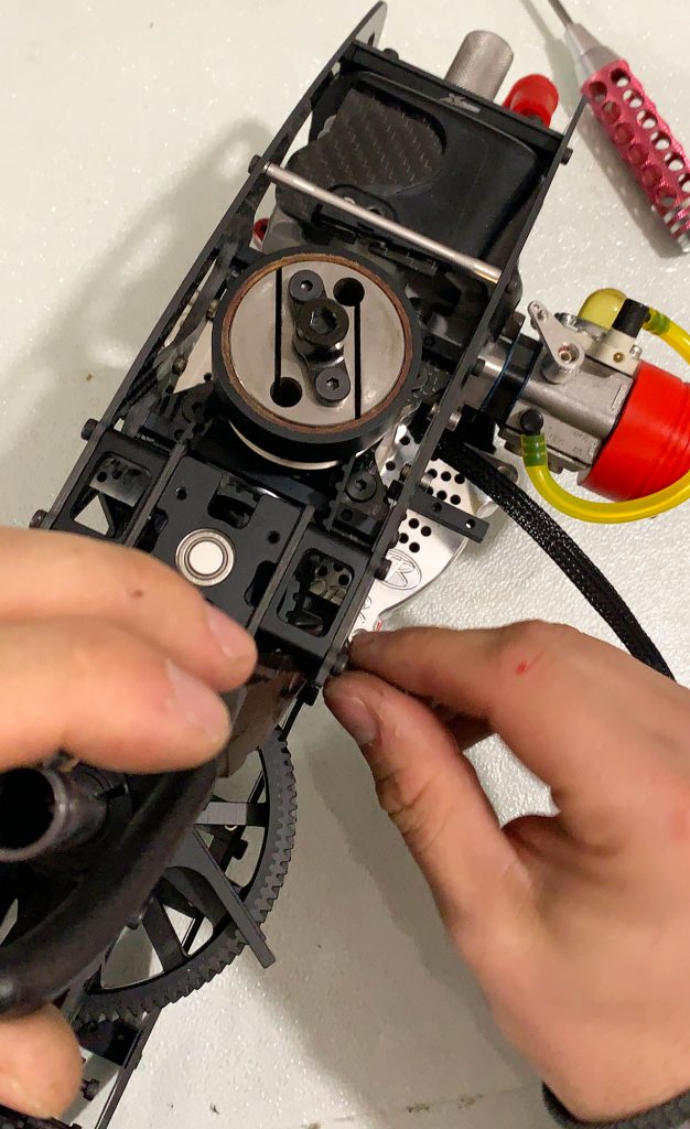
- Throw the Belt inside the upper frame and pass it around the pulleys..
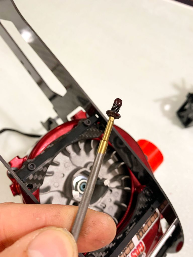
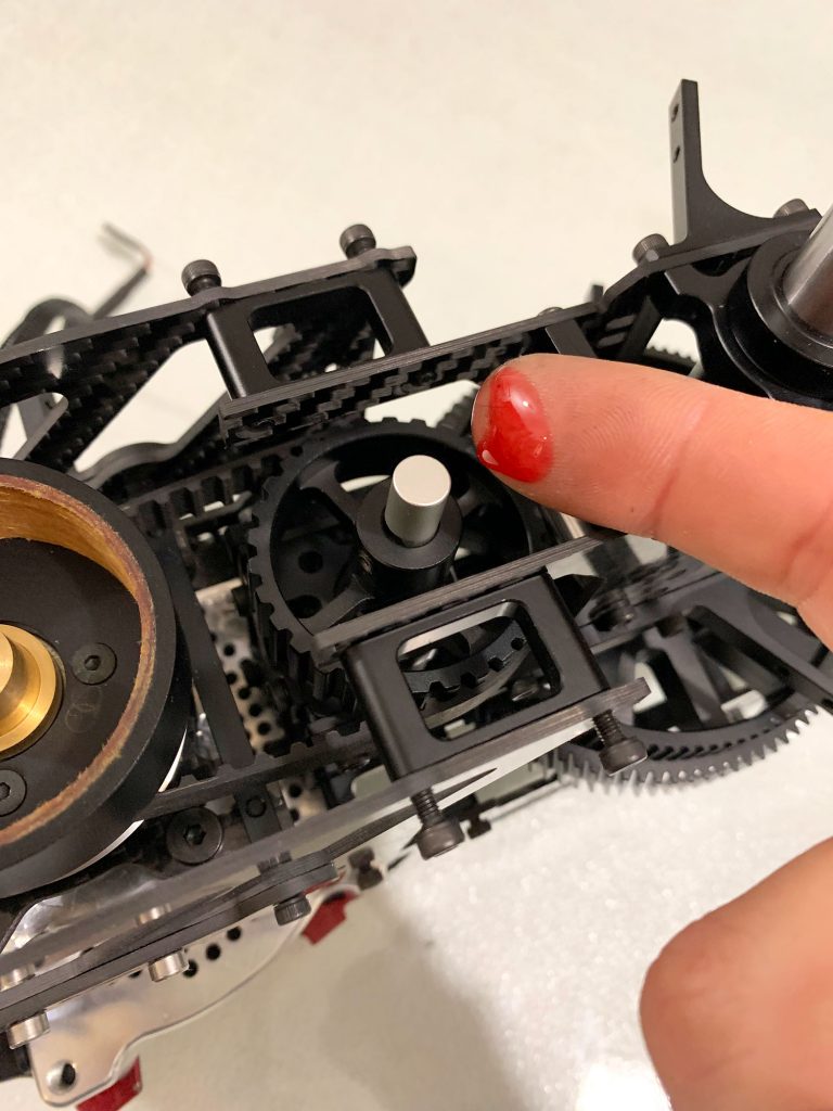
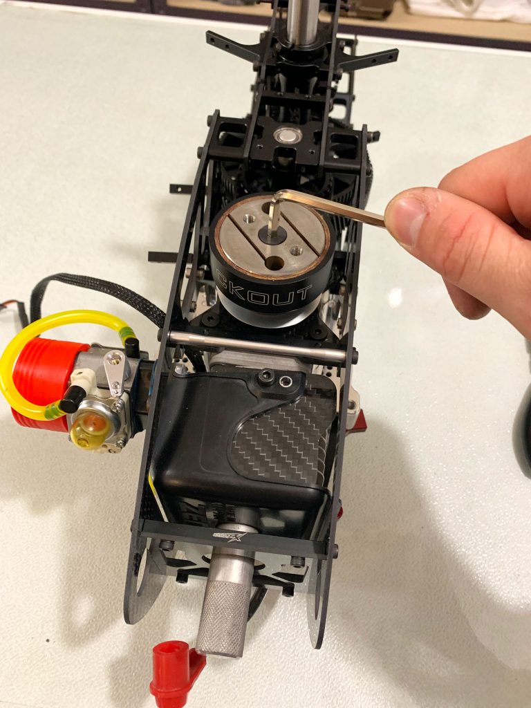
Apply a little amount of lock tite with your finger on the shaft in order to secure the inner bearing race of the top ball bearing.
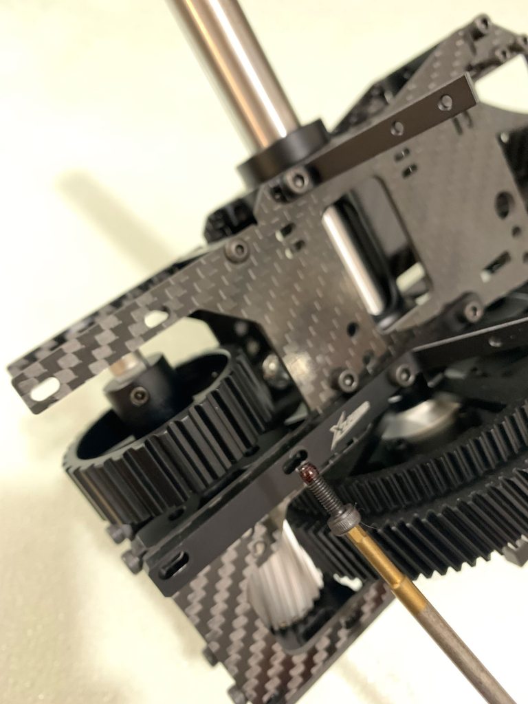
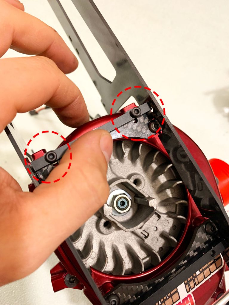
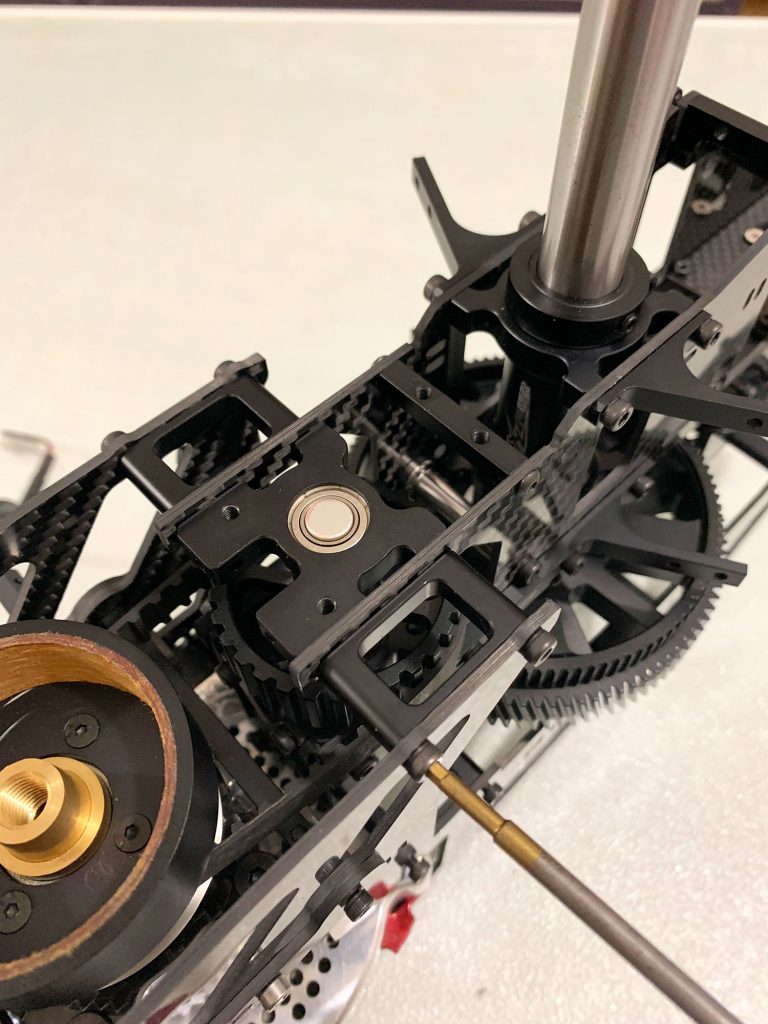
Mount the Bearing block in place and the frame spacers with the proper bolts to hold them all together and full tight down all the frame bolts except the upper and lower engine side mounting bolts.. keep only the engine side frame bolts loose in order to adjust the belt tension by moving the whole engine a bit to the front (next step)..
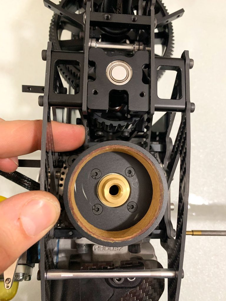
- Normally the Belt is too loose and you have to adjust the tension of it in order to be tight enough for safe and smooth transfer of the power.
Make sure that all the side bolts of the engine top and bottom mounts are loose and with your hands pull the engine to the front.
The engine with the mounts should move slightly to the front and the belt tights up niselly. You can do this without the Clutch mounted yet so the whole assy be lighter and the alignment be a bit easier..
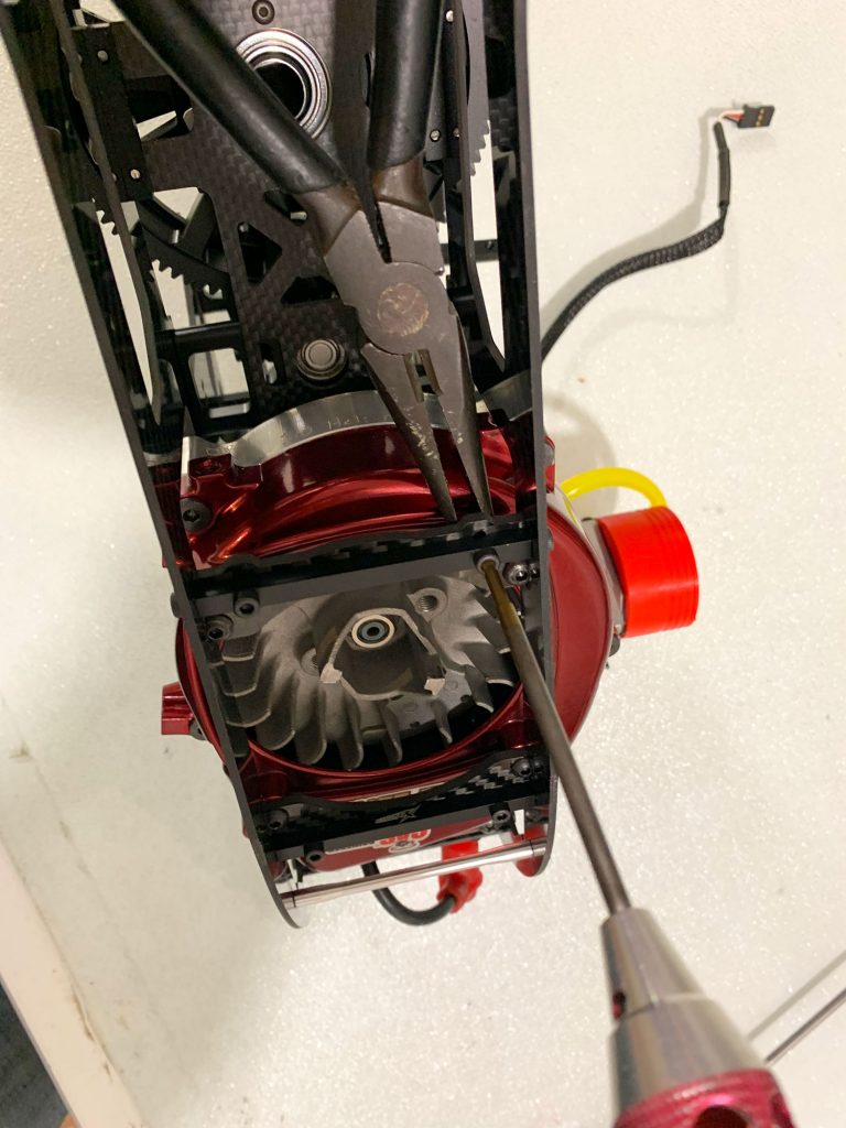
Keeping the force with your hand against the frame, tight down the side engine mounting bolts starting from the midles at the side of top engine mount (one by one cross sides….
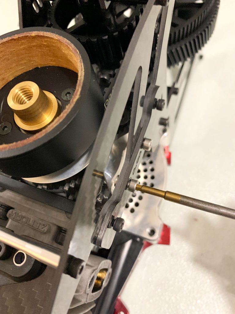
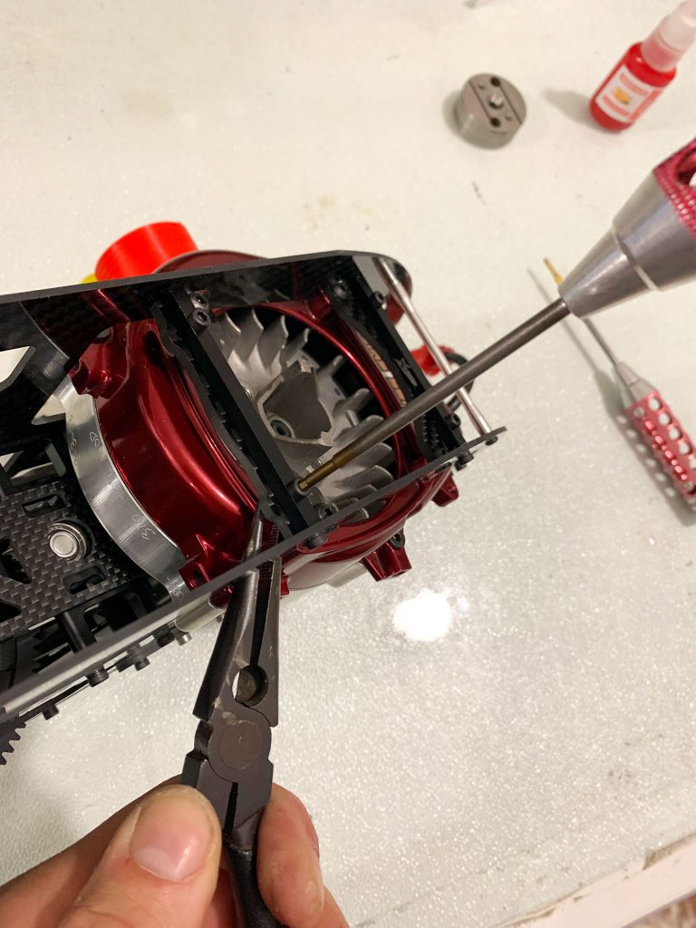
- If you did the drill mod at the metal spacers you will have easy time by tighting down the M3 bolts to the carbon fiber lower moutns slotted holes using a plier and M3 Driver. If not you will face a bit of hassle by do and undo these bolts in order to find the perfect spot to aligh the lower engine mounts with the side holes of the frame..
With the metal spacers full tighten on the carbon fiber lower engine mounts now you can full tight the side M3 Bolts too.
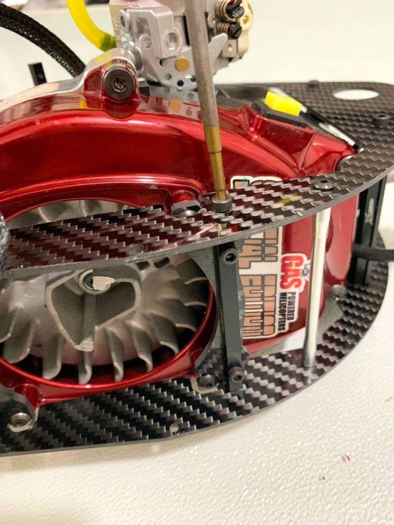
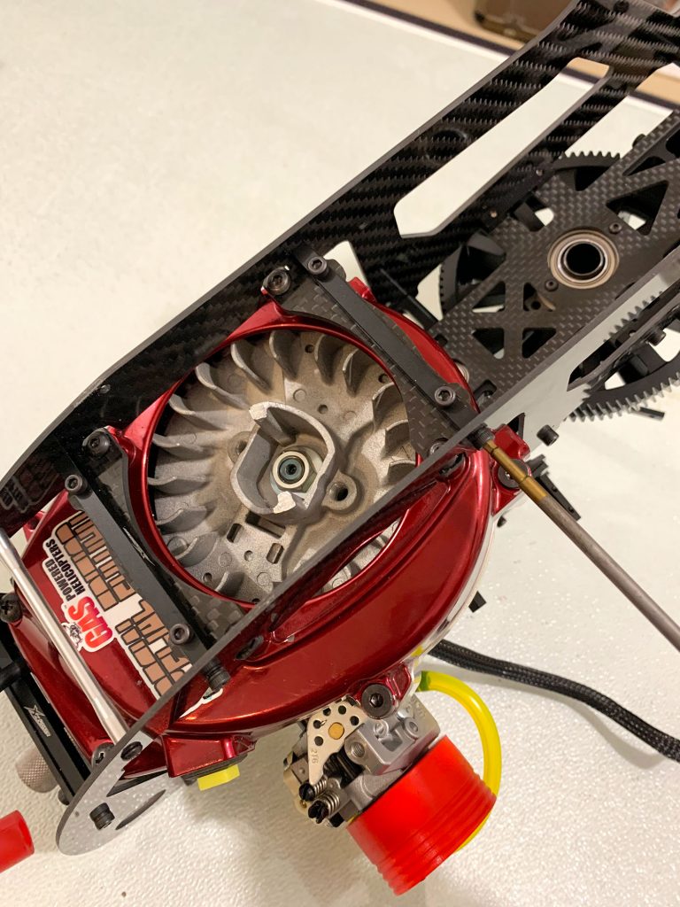
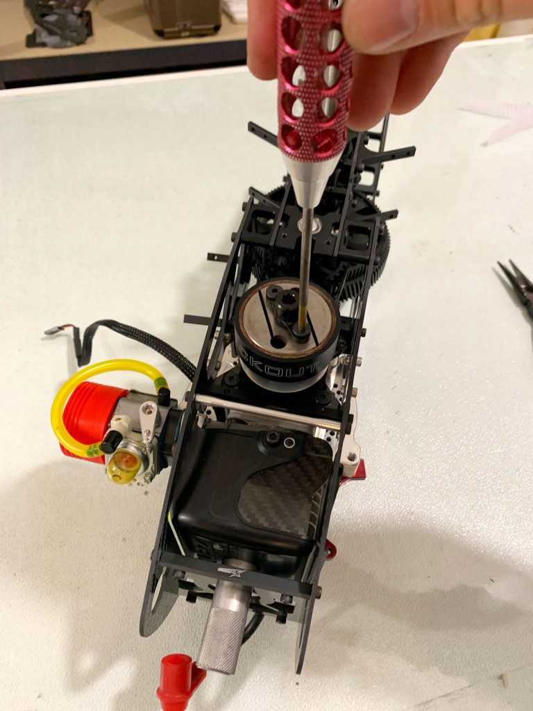
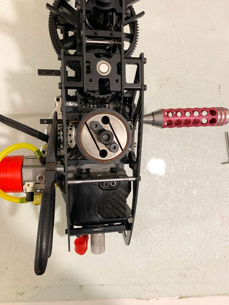
- With the engine full tighted down and all the bolts lock tited now you can add the clutch and the top start adaptor.
Using a piston Stopper will helps to do this easy.
Do not over tight these bolts in order to avoid to damage the piston by extreme pressure against the piston stoper!
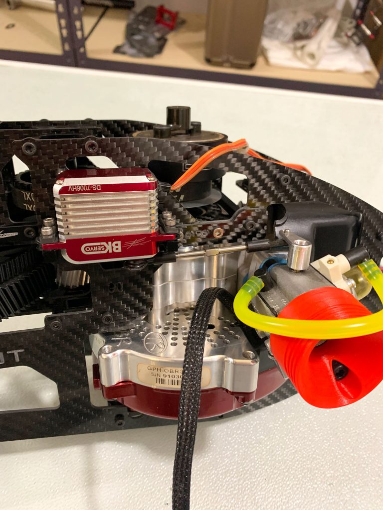
- Now tight down the Throttle Servo Metal mounts using small amount of lock tite.
The one bolt is accessible from the oposite side of the frame and with a plier you can tight the mount down making sure that is sets straight for the servo..
The other bolt is more tricky as the space there is limited but with a plier holding the bolt head from inside and your hand holding the metal mount its not so hard to tight down this too.
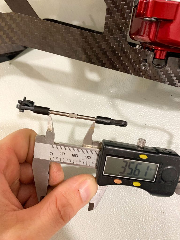
Use a Main rotor head linkage rod and 2 Ball links for the throttle servo connection with the carb.
Start with 35.6MM distance between the ball links and fine tune the lenght as you like.
If your Throttle servo interfaces with the side engine mount bolt behind it, replace the normal bolt with a button head bolt that is lower the head lenght.
- FBL Mount included with some antivibration spacers under of it.
Using a proper Hex Screw driver tight down the plate using a bit of lock tite.
You dont have to over tight it..just make sure that is nice and straight mounted.
Dennis
😉