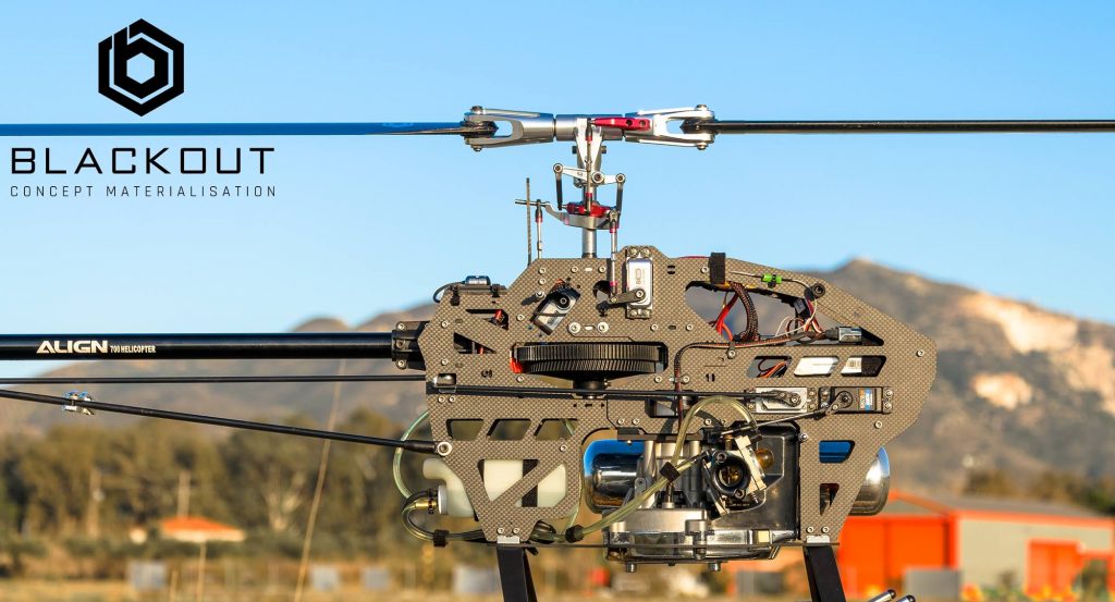
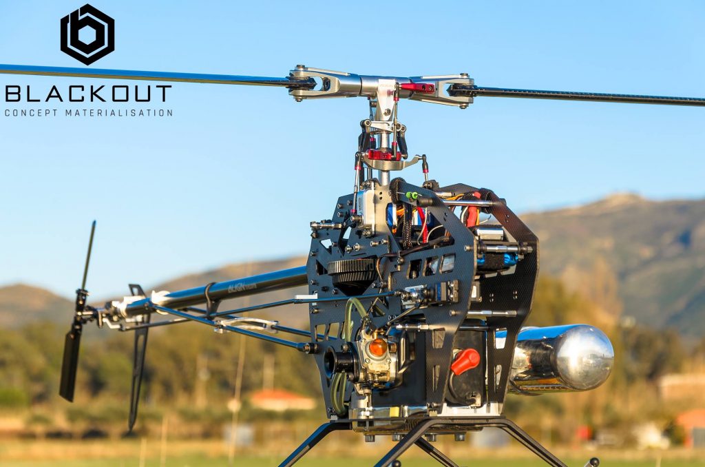
G700Z. At last… a Reliable Gasser Helicopter!
After lots of Drawings, Prototyping and Hours of Test Flights we’ve finally Made it!
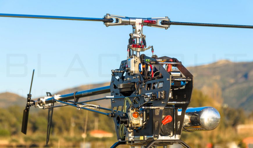
We Designed a truly Reliable Gasser Helicopter with 3D flight capability!
The proper Characteristics for an Everyday Gasser Helicopter are :
- Easy finding spare parts
- Easy and quick maintenance
- Easy to transport without fuzz
- Practical frame design for the accessories
- Reasonable prices when repair issues occur
- Reasonable prices in use – cost per flight
- Reliable electronics and mechanical parts
- 3D / acrobatic flight capabilities
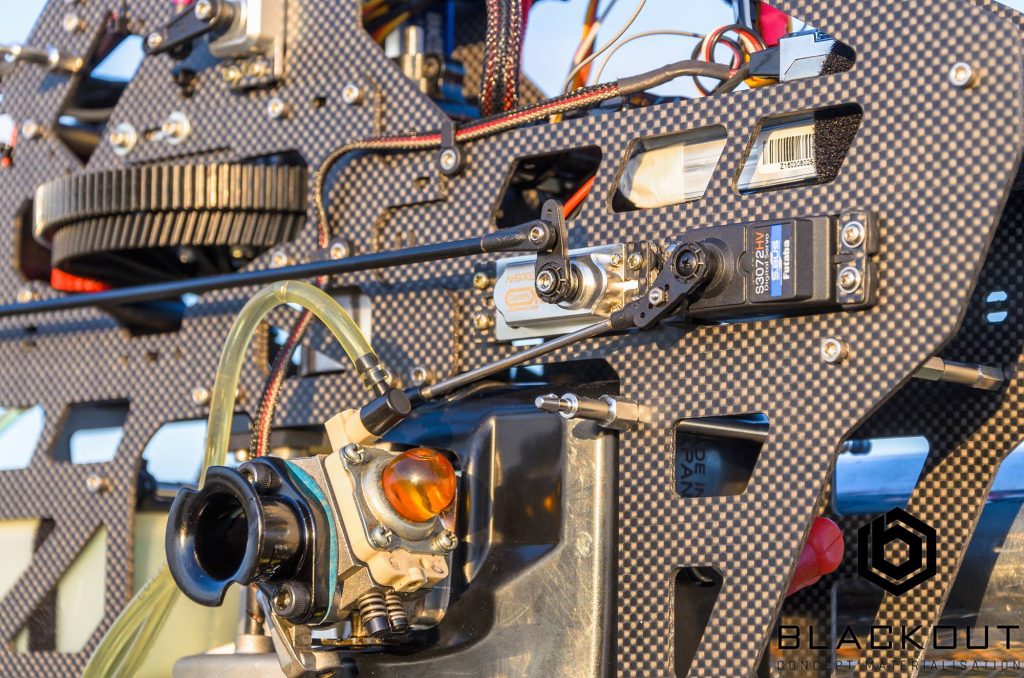
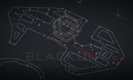
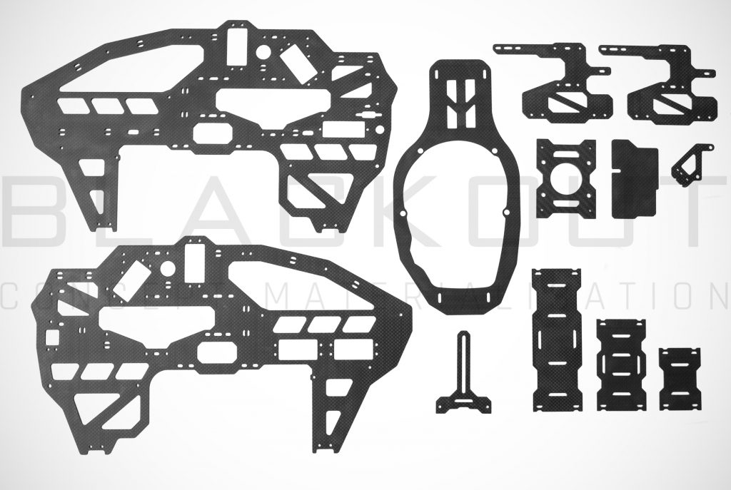
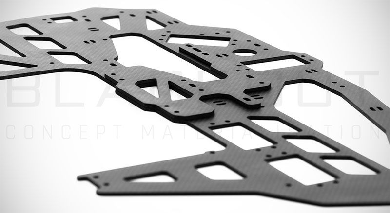
Full Carbon Fiber Parts
Constructed from 100% wooven carbon fiber fabrics & High quality resins via Vacuum infusion process, all main frame parts has a High Rigidity levels and looks good also.
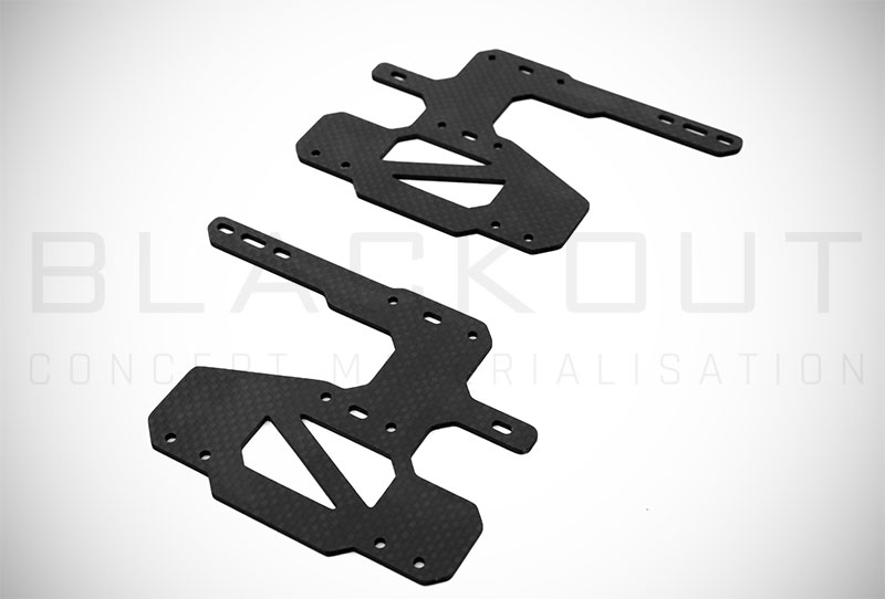
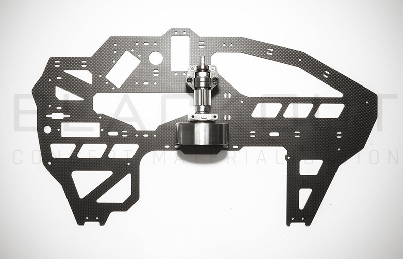
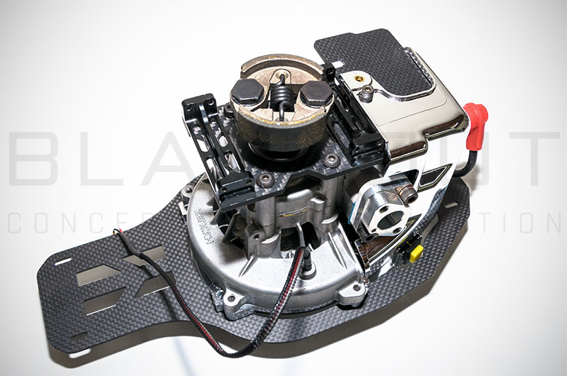
Engine / Gear box Alignment & Reinforcement plates
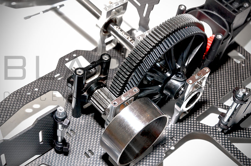
With slotted design the gearbox section has been enhanced in Rigidity and the Gears Distance now is adjustable for Fine Tuning the Gear Mesh or using different gear ratios with no issues at all.
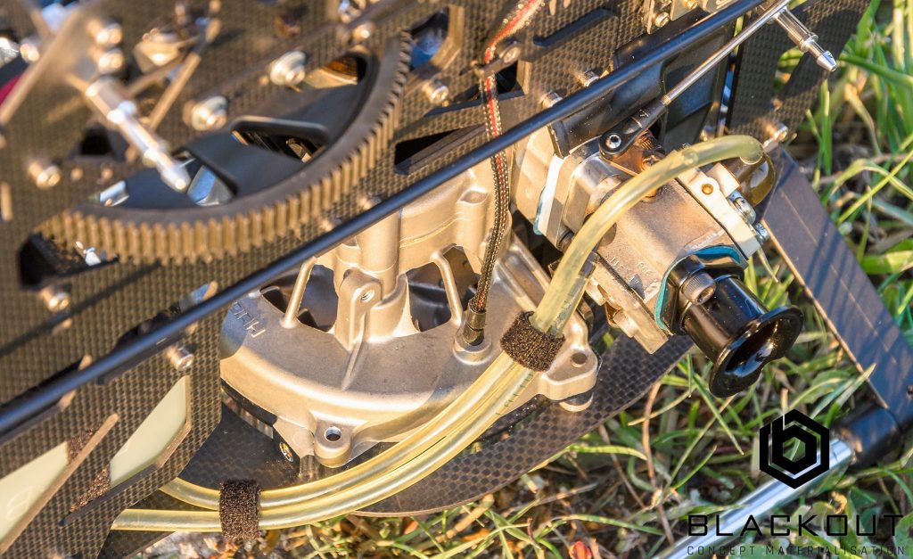
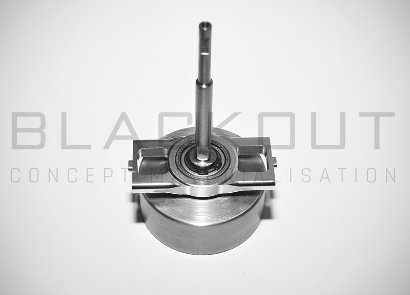
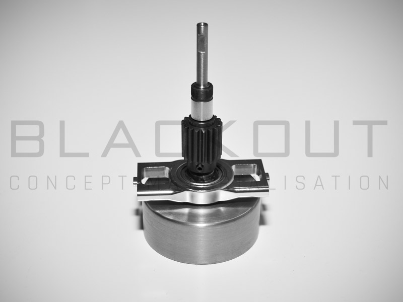
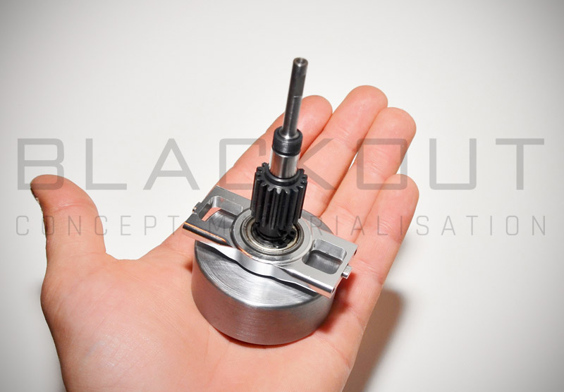
Special Gearbox System with Clutch Bell & 17T Pinion Gear
The clutch bell made from one piece Steal and machined by lathe with a single grip ensuring true running even at 15000 Rpm.
The Pinion Gear has 17 teeth / Mod 1MM and machined by CNC. The gear fastens in correct position with a M4 worm Screw with hex Socket like the pinions on electric motors.
The Clutch bell is secured in place with a C-clip above the first bell support Bearing and stay straight with 3 more bearings above the pinion gear. Total two Bearing blocks used..
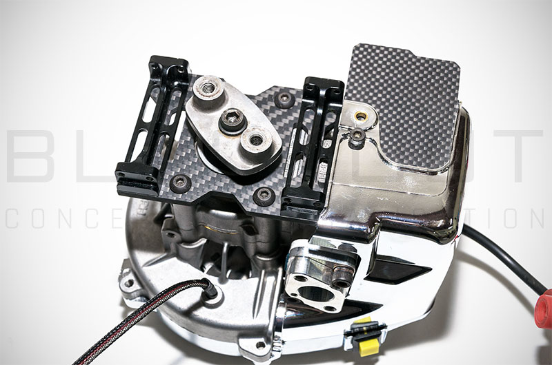
Magnetic Governor Sensor Mount.
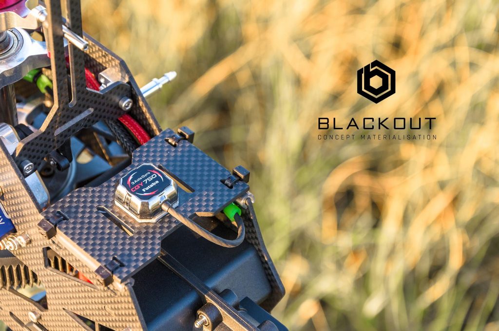
After a lot of Testing, we found that circuits like Stator Gator are too noisy and works well ONLY with Futaba GV1 Governor Unit..
We suggest do not use them on FBL Unit or other Flight Stabilization System with direct connection (without Futaba’s GV1)..
The most clear solution to enjoy Governor Function with your Gasser is the magnetic sensors.
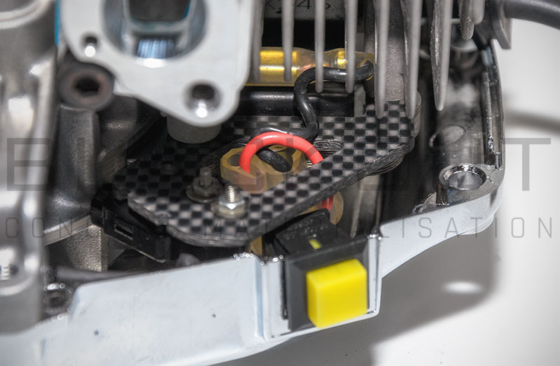
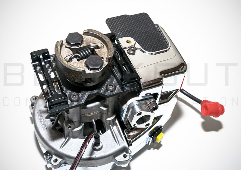
As the mounting on a gasser helicopters with custom clutch bells is a problem, we design a nice carbon fiber mount that supports all magnetic sensors of the market and now you can have a safe Governor for your Gasser Helicopter reading the engine’s RPM direct from the engine’s flywheel magnets.
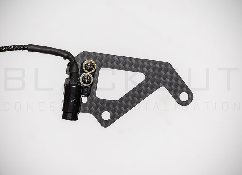
- Remove the magnetic coil from the engine and the spacers too.
- Put the Governor sensor mount in place without the spacers ( the mount its self is the spacer now..)
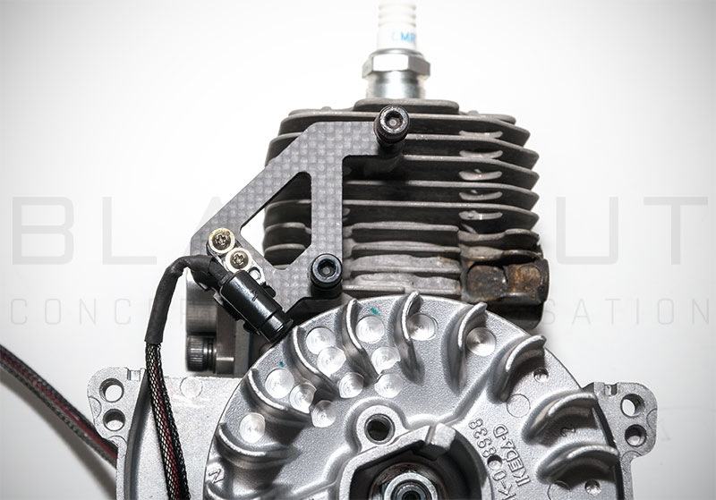
- Put the coil back in place above the governor mount and screw the bolts but not tight at all..
- Put on the Kill Swich too if you want to use it.
- The assembly must be movable in this stage..
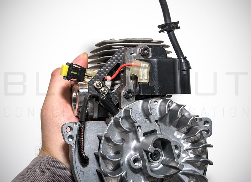
- Put one piece of Paper between the coil and the flyweel (at the position with magnets..)
- The magnets will pull the coil and the governor mount in and the distance between them will be the minimum as the thickness of the paper is..
- Now Full tight the bolts (no locktite needed) and remove the paper
- The flyweel must turns with no problem and the governor sensor has 2MM distance Max.
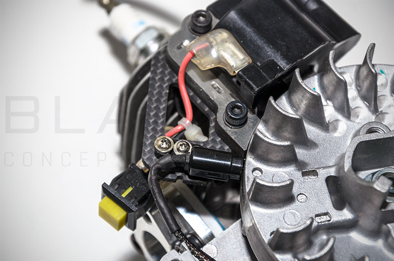
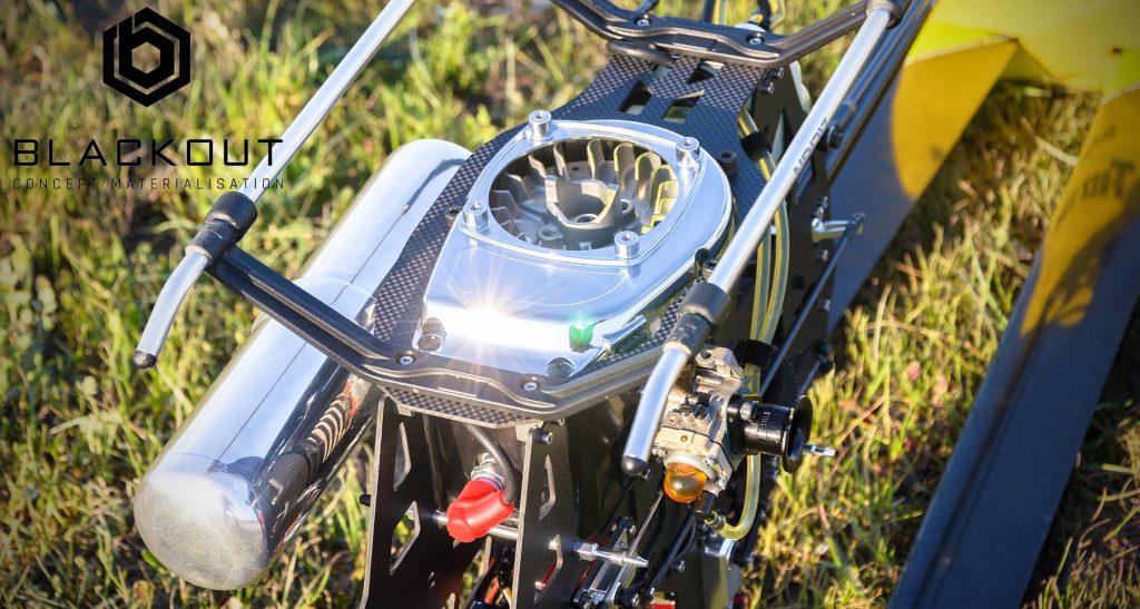
Engine Heat Deflector
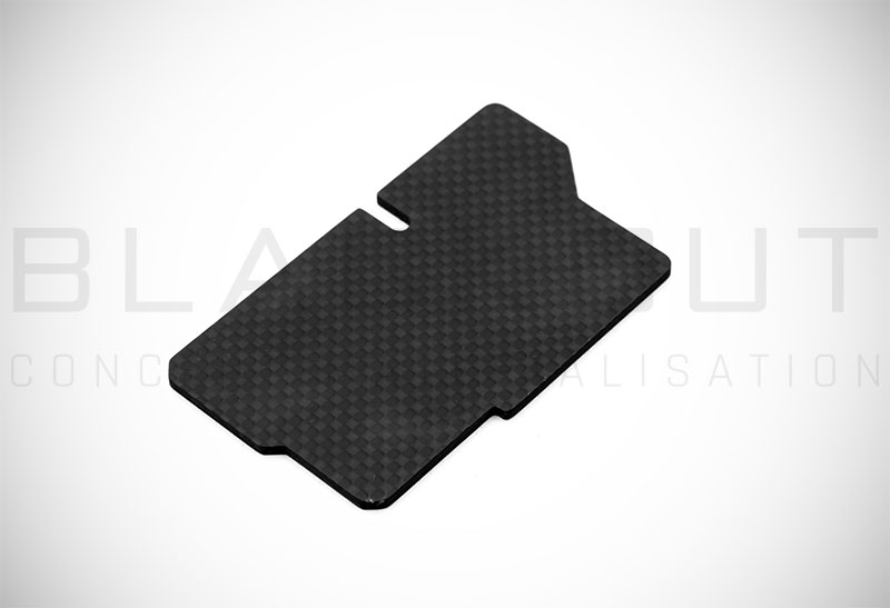
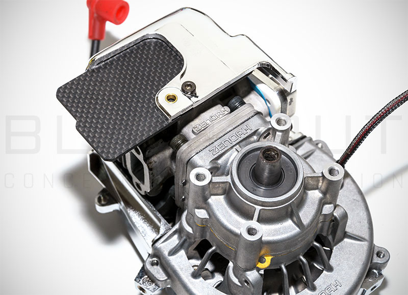
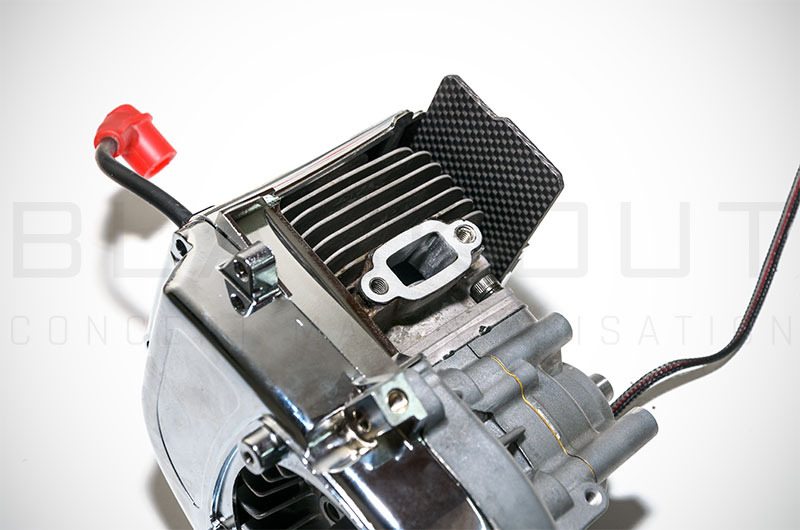
Due engine’s orientation, the hot air from the engine goes inside the canopy making the area of the electronics warmer…
With this little carbon fiber piece the hot air directed outside from the canopy and prevent the overheating of the electronics.
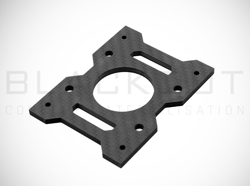
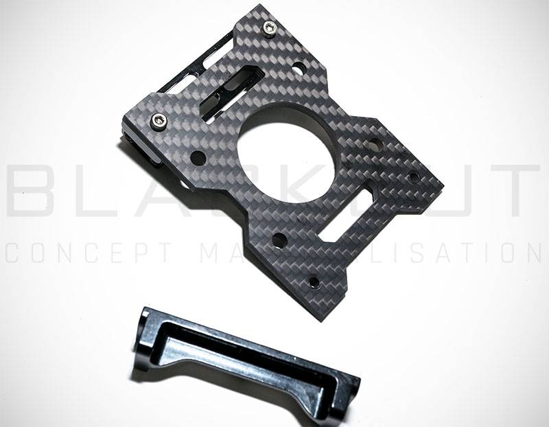
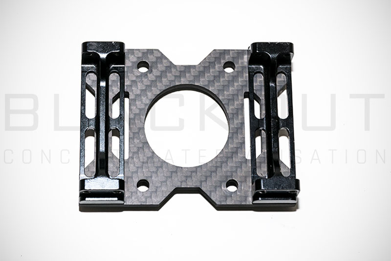
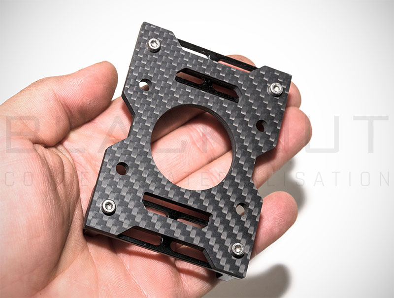
Engine Master Mount
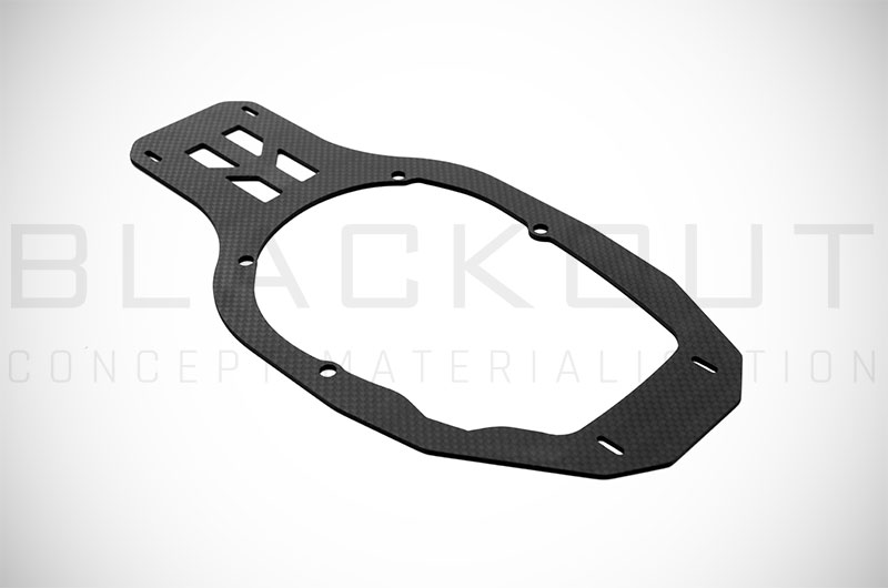
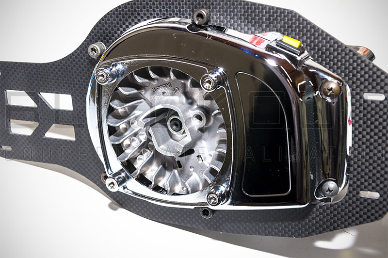
Full Carbon Fiber Engine Master Mount 4MM in total thickness (one 4MM thick piece or two pieces of 2MM stacked depens of production) is more than enough for a true rigid mounting system..
Using two extra frame mounts of Align the Master Engine Mount is ready to hold the engine in place with no flex at all..
Engine Bottom Frame
With this part we have completed the engine assembly..
So, Lets buid the G700Z!
- Start put on the one Frame all the Bearing blocks, frame spacers, one (HN6019) Frame Mounting Block with the anti-rotation Bracket and the tail boom section but no fully tight any of the bolts yet.
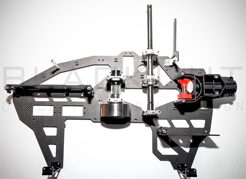
- For the Electronics Carbon Fiber Mounts use the (HZ022A) Skid Dampers as vibration isolators and secure them with the carbon plates on the (HN7048T) Aluminum Hexagonal spacers with small Cable ties.
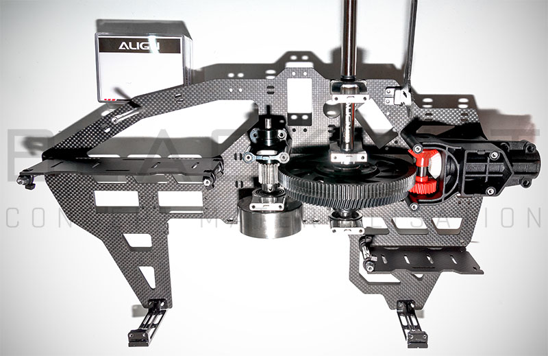
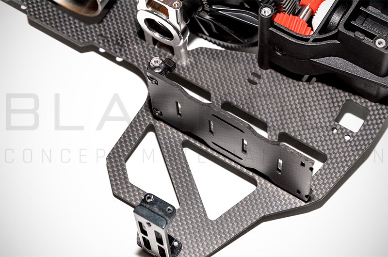
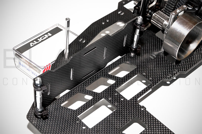
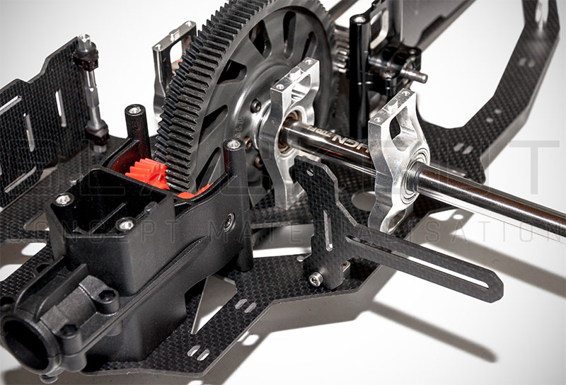
- Put the fuel Tank in place with some double sided foamy adhesive Tape on the carbon Fiber Mount and loop it with velcro.
The edges of the carbon fiber Mount are Pre sanded to avoid cutting of the velcro but always an extra check is required for safety..
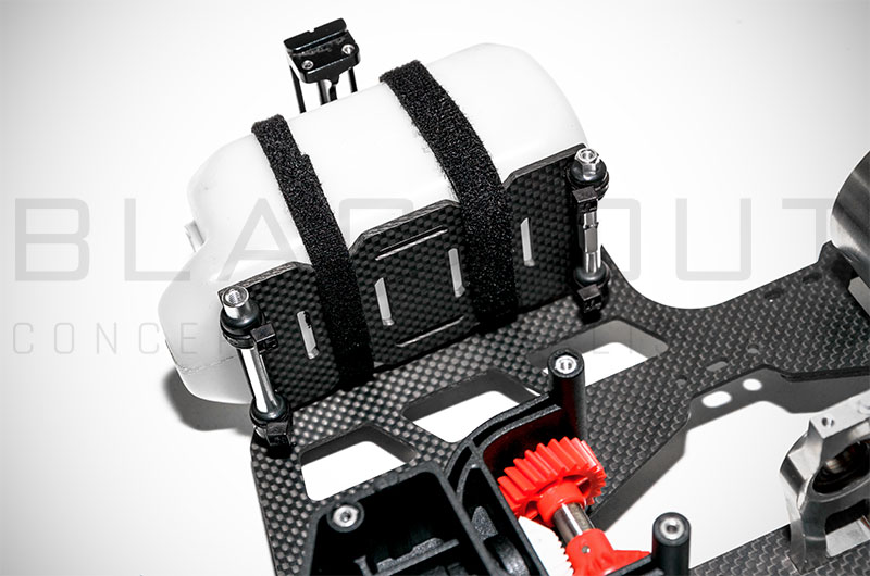
- Now you can put in place the Engine assembly and the second main Frame.
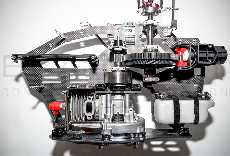
- After you make sure that the Gear mesh is correct (with a folded piece of paper) between Pinion gear and Main Gear but also between Auto rotation Gear and Tail gear secure all the bolts but no in full tight and no thread lock yet!
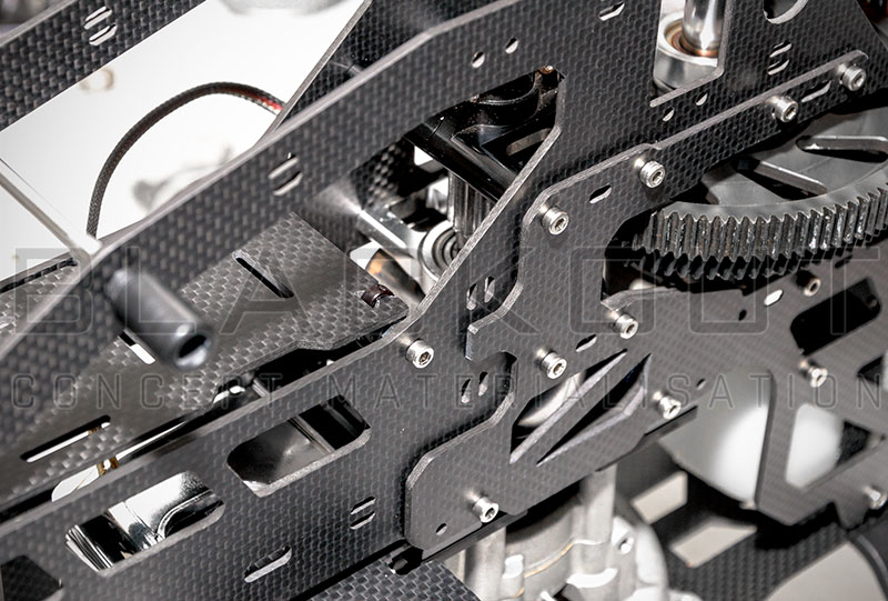
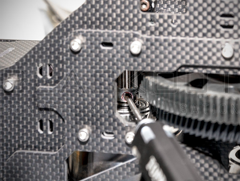
- Now the pinion gear it has the perfect position on the Clutch Bell. So now you can lock tite the worm screw and recure the pinion gear.
- After you secure the Pinion Gear remove all the papers from the gears and test the movement of the systems.. If they are good spinning you can lock tite and full tight all bolts one by one! If not, you have to release the bolts and put again the papers between the gears..
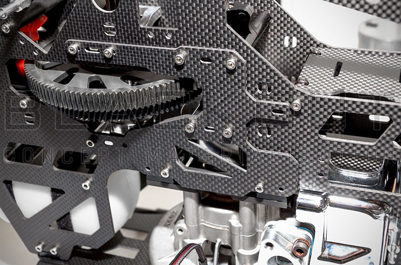
Ok, now lets Fly!
